
DE Tutorial (Gate Wallah) ▶️
Digital Electronics One Shot | EE / ECE / IN / ECE | CS | Maha Revision | Target GATE 2025
Section titled “Digital Electronics One Shot | EE / ECE / IN / ECE | CS | Maha Revision | Target GATE 2025”Created using Google NotebookLM
1. Introduction
Section titled “1. Introduction”The session will cover:
- Theorems and Gates.
- Combinational Circuits (Mux, K-Map, Comparator, Full Adder, Half Adder).
- Sequential Circuits (Latches, Flip-Flops, Asynchronous & Synchronous Counters).
- Miscellaneous topics like Number Systems and possibly ADC/DAC if time permits.
2. Basic Theorems and Gates
Section titled “2. Basic Theorems and Gates”The focus is on the most important theorems for revision.
2.1 Fundamental Boolean Algebra Theorems
1 + Anything = 1- If a Boolean expression involves OR operations and contains a ‘1’, the result is always ‘1’.
- Example:
1 + A + B' + Cwill simplify to1.
0 * Anything = 0- If a Boolean expression involves AND operations and contains a ‘0’, the result is always ‘0’.
- Example:
0 * A * B' * Cwill simplify to0.
A + A' = 1andA * A' = 0- A variable
ORed with its complement is always ‘1’. - A variable
ANDed with its complement is always ‘0’. - These are crucial for simplification.
- Example:
A' + B' + AB- This can be written as
(AB)' + ABusing De Morgan’s theorem. - Applying
X' + X = 1, the result is1.
- This can be written as
- A variable
- Associative Property for OR and AND Operations
- The order of operations does not affect the result.
- Example:
A + B + Ccan be(A + B) + CorA + (B + C). - Example:
A * B * Ccan be(A * B) * CorA * (B * C).
2.2 Distributive Theorem
- AND over OR (Normal Distributive Law)
A * (B + C) = A * B + A * C.- This is intuitive, like basic algebra.
- OR over AND (Boolean Algebra Specific)
A + (B * C) = (A + B) * (A + C)⭐- This is a very important theorem, used extensively in GATE questions.
- Reverse Direction Application: This theorem is frequently asked in its reverse form, where multiple brackets are multiplied, and a common term exists.
- If common term is
A, then(A + B) * (A + C)can be simplified toA + BC. ⭐
- If common term is
- Numerical Example for Reverse Direction:
F = (A + B + C') * (A + B' + C) * (A + B + C)- Step 1: Operate on the first two brackets. Notice
(A + B)is common in the first and third bracket, but it’s better to operate on two at a time. - Consider the first two:
(A + B + C') * (A + B' + C)- Common term is
A. What remains areB + C'andB' + C. - Applying the reverse distributive law:
A + (B + C') * (B' + C) - Now simplify
(B + C') * (B' + C)using the cross-product theorem (discussed later) or simply by expanding:BB' + BC + C'B' + C'C0 + BC + B'C' + 0BC + B'C'(This is B XNOR C)
- So the first two brackets simplify to
A + (BC + B'C').
- Common term is
- Step 2: Multiply this result with the third bracket:
(A + BC + B'C') * (A + B + C)- Here,
Ais common. - Applying the reverse distributive law again:
A + (BC + B'C') * (B + C) - Now simplify
(BC + B'C') * (B + C):BC * B + BC * C + B'C' * B + B'C' * CBC + BC + 0 + 0(sinceBB=B,CC=C,B'B=0,C'C=0)BC
- So the final result is
A + BC.
- Here,
2.3 Absorption/Redundancy Theorem
- Theorem:
A + A'C + BC = A + A'C(whereBCis the redundant term). - Conditions for Applicability:
- At least one variable must be present in both complemented and uncomplemented forms (e.g.,
AandA'). - The product of the remaining variables (those not in complemented/uncomplemented pair) must be present as a term.
- At least one variable must be present in both complemented and uncomplemented forms (e.g.,
- Example 1:
A + A'C + BCAandA'are present.- Remaining variables are
B(withA) andC(withA'). - Their product
BCis present. - Therefore,
BCis the redundant term and can be removed. - Result:
A + A'C.
- Example 2:
A'C + BC' + A'B- Identify complemented/uncomplemented pair: Only
CandC'are present in both forms. - Check remaining terms: With
C,A'remains. WithC',Bremains. Is their productA'Bpresent? Yes. - Therefore, ==
A'Bis the redundant== term. - Result:
A'C + BC'. - Note: The redundant term is not always the last term.
- Identify complemented/uncomplemented pair: Only
- Example 3 (Non-Applicable Redundancy):
A'C + BC' + ABCCandC'are present.- Remaining terms are
A'andB. Their product isA'B. ABCis present, notA'B. So, Redundancy Theorem does not directly apply here.- Alternative Simplification (Distributive Law):
A'C + BC' + ABC- Take
Acommon fromA'C(oops, mistake by speaker,Acannot be taken common fromA'C). - The speaker then took
Acommon fromABCto formA(BC). - Let’s re-evaluate the speaker’s logic for
A'C + BC' + ABC. - They say:
A'C + B(C' + AC). Speaker’s solution path for this example on transcriptA'C + BC' + ABCwas to noteRedundancy Theorem Not Applicable. Then, they tried to identifyAcommon from some terms. The example they worked on wasA'B + A'C + BC. - The actual solution given for
A'C + BC' + ABCwasA + BCby combiningA + B + C'andA + B' + Cwhich is a different example. - For
A'C + BC' + ABC, the actual simplification path might be takingCcommon:C(A' + AB) + BC'.A' + AB = A' + B(Absorption Law:X' + XY = X' + Y).- So,
C(A' + B) + BC' A'C + BC + BC'A'C + B(C + C')A'C + B(1)A'C + B.
- This shows that even if Redundancy Theorem doesn’t apply, other theorems might.
2.4 Cross-Product Theorem (Consensus Theorem - AB + BC + C'A = AB + C'A)
- Theorem:
(A + B) * (A' + C) = AC + A'B- This theorem applies when two brackets are in product, and one variable exists in both complemented and uncomplemented forms (e.g.,
AandA'). - The terms
A*A'become0. The remaining termsACandA'Bare the result. - In essence, this is an application of distribution:
AA' + AC + BA' + BC = 0 + AC + A'B + BC. Here,BCis the redundant term. - Reverse Version (Important): If you have an expression like
A'B' + AC', you can convert it back to(A' + C') * (B' + A)(re-order(A + B')).- To apply the reverse: Identify a variable present in both complemented and uncomplemented forms (
AandA'). This variable will appear in separate brackets. A'B' + AC'(HereAandA'are the variables).- One bracket will have
A', another will haveA. A'is withB', so(A' + B').Ais withC', so(A + C').- Result:
(A' + B') * (A + C').
- To apply the reverse: Identify a variable present in both complemented and uncomplemented forms (
- This theorem applies when two brackets are in product, and one variable exists in both complemented and uncomplemented forms (e.g.,
3. Logic Gates
Section titled “3. Logic Gates”3.1 AND Gate
- Symbol & Truth Table (2-Input):
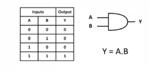
- Multi-Input Property: For an N-input AND gate:
- Output will be 1 ONLY IF ALL the inputs are High (1).
- If ANY ONE of the inputs is Zero, the output will DEFINITELY be Zero, regardless of other inputs.
- Enable/Disable Input:
- Enable Input: 1 (If one input is permanently held at 1, the output will reflect the AND of the other inputs, enabling the gate’s function).
- Disable Input: 0 (If one input is permanently held at 0, the output will always be 0, disabling the gate’s function).
- Laws: Holds Commutative Law (
A.B = B.A) and Associative Law (A.(B.C) = (A.B).C).
3.2 OR Gate
Symbol & Truth Table (2-Input):
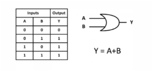
- Multi-Input Property: For an N-input OR gate:
- Output will be 0 ONLY IF ALL the inputs are Low (0).
- If ANY ONE of the inputs is One, the output will DEFINITELY be One, regardless of other inputs.
- Enable/Disable Input:
- Enable Input: 0 (If one input is permanently held at 0, the output will reflect the OR of the other inputs, enabling the gate’s function).
- Disable Input: 1 (If one input is permanently held at 1, the output will always be 1, disabling the gate’s function).
- Laws: Holds Commutative Law (
A+B = B+A) and Associative Law (A+(B+C) = (A+B)+C). - Special Theorem:
P + P * Anything = P- This is not a fundamental theorem but a very useful identity for simplification.
- Example:
A + A * Bsimplifies toA.
3.3 NAND Gate
Symbol & Truth Table (2-Input):

- Construction: AND gate followed by a NOT gate (
AND + NOT). - Output Expressions:
Y = (A . B)'- Using De Morgan’s Theorem:
Y = A' + B' - For multi-input (e.g., 3-input):
Y = (A . B . C)'orY = A' + B' + C'.
- Output Writing Technique:
- Method 1: Multiply all inputs, then take the whole complement.
- Method 2: Invert each input, then add them (useful when inputs are already complemented).
- Example:
NAND(A_bar, B_bar)will beA + B(A_bar inverted is A, B_bar inverted is B, then add). - Example:
NAND(A, B_bar, C_bar)will beA_bar + B + C.
- Example:
- Multi-Input Property: For an N-input NAND gate:
- Output will be 0 ONLY IF ALL the inputs are High (1).
- If ANY ONE of the inputs is Zero, the output will DEFINITELY be One, regardless of other inputs.
- Enable/Disable Input: Same as AND gate.
- Enable Input: 1
- Disable Input: 0.
- Rationale: If a NAND gate’s AND part is enabled/disabled, the NOT part just inverts the result, maintaining the overall enable/disable behavior.
- Laws: Holds Commutative Law (
(A.B)' = (B.A)'). Does NOT hold Associative Law.
3.4 NOR Gate
Symbol & Truth Table (2-Input):
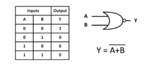
- Construction: OR gate followed by a NOT gate (
OR + NOT). - Output Expressions:
Y = (A + B)'- Using De Morgan’s Theorem:
Y = A' . B' - For multi-input (e.g., 3-input):
Y = (A + B + C)'orY = A' . B' . C'.
- Output Writing Technique:
- Method 1: Add all inputs, then take the whole complement.
- Method 2: Invert each input, then multiply them (useful when inputs are already complemented).
- Example:
NOR(A_bar, B_bar)will beA . B. - Example:
NOR(A, B_bar, C_bar)will beA_bar . B . C.
- Example:
- Multi-Input Property: For an N-input NOR gate:
- Output will be 1 ONLY IF ALL the inputs are Low (0).
- If ANY ONE of the inputs is One, the output will DEFINITELY be Zero, regardless of other inputs.
- Enable/Disable Input: Same as OR gate.
- Enable Input: 0
- Disable Input: 1.
- Laws: Holds Commutative Law (
(A+B)' = (B+A)'). Does NOT hold Associative Law.
3.5 XOR Gate
Symbol & Truth Table (2-Input):
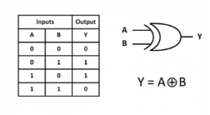
- Construction (from basic gates):
A XOR B = A'B + AB'- Diagram: AND gates generate
A'BandAB', followed by an OR gate.
- Definition:
- Output is 1 when the inputs are DIFFERENT (0 XOR 1 = 1, 1 XOR 0 = 1).
- Output is 0 when the inputs are SAME (0 XOR 0 = 0, 1 XOR 1 = 0).
- Multi-Input XOR:
- NOT directly defined. It’s always calculated by applying the XOR operation two inputs at a time using the Associative Law.
- Example:
A XOR B XOR Cis calculated as(A XOR B) XOR C. - Symmetry (Odd Number of Ones Detector): When calculating multi-input XOR, an observation (not a definition) is that the output is 1 if the total number of ‘1’s in the input is odd, and 0 if the total number of ‘1’s is even.
- Laws: Holds Commutative Law (
A XOR B = B XOR A) and Associative Law (A XOR (B XOR C) = (A XOR B) XOR C). - Properties:
A XOR A = 0(Same inputs, output 0).A XOR A' = 1(Different inputs, output 1).A XOR 0 = A(Acts as a buffer).A XOR 1 = A'(Acts as an inverter).- Exchange Property: If
A XOR B = C, thenA XOR C = B(andB XOR C = A).
- Important Special Properties:
A XOR B XOR AB = A + B.A XOR B XOR (A + B) = AB.
- Distributive Law for XOR (Does NOT Hold): XOR operation cannot be distributed over AND or OR operations (
A XOR (B + C)is NOT(A XOR B) + (A XOR C)).- Correct Way to Solve
A XOR (A + B):- Treat
Aas the first term and(A + B)as the second. - Apply
First' * Second + First * Second' A' * (A + B) + A * (A + B)'A'A + A'B + A * (A'B')(using De Morgan’s for(A + B)')0 + A'B + AA'B'A'B + 0- Result:
A'B.
- Treat
- Correct Way to Solve
3.6 XNOR Gate
Symbol & Truth Table (2-Input):
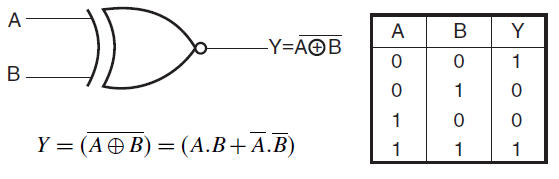
- Construction (from basic gates):
A XNOR B = A'B' + AB- Diagram: AND gates generate
A'B'andAB, followed by an OR gate.
- Definition:
- Output is 1 when the inputs are SAME (0 XNOR 0 = 1, 1 XNOR 1 = 1).
- Output is 0 when the inputs are DIFFERENT (0 XNOR 1 = 0, 1 XNOR 0 = 0).
- Relation to XOR: XNOR is the complement of XOR (
A XNOR B = (A XOR B)'). - Multi-Input XNOR:
- NOT directly defined. Calculated using Associative Law (two inputs at a time).
- Symmetry:
- For Odd number of input lines: XNOR acts as an Odd Number of Ones Detector (output 1 if odd number of 1s, 0 if even number of 1s). In this case,
A XNOR B XNOR Cis equal toA XOR B XOR C. - For Even number of input lines: XNOR acts as an Even Number of Ones Detector (output 1 if even number of 1s, 0 if odd number of 1s). In this case,
A XNOR B XNOR C XNOR Dis equal to(A XOR B XOR C XOR D)'.
- For Odd number of input lines: XNOR acts as an Odd Number of Ones Detector (output 1 if odd number of 1s, 0 if even number of 1s). In this case,
- Properties:
A XNOR A = 1(Same inputs, output 1).A XNOR A' = 0(Different inputs, output 0).A XNOR 0 = A'.A XNOR 1 = A.- Exchange Property: If
A XNOR B = C, thenA XNOR C = B(andB XNOR C = A).
3.7 Mixed Properties of XOR and XNOR

- Complementing one input:
A XOR B' = A XNOR B.A' XOR B = A XNOR B.A XNOR B' = A XOR B.A' XNOR B = A XOR B.
- Complementing both inputs:
A' XOR B' = A XOR B.A' XNOR B' = A XNOR B.
- General Complement Property (Number of Bars):
- Count the total number of complement bars on variables and whole expressions.
- If the total count of bars is EVEN, the gate type remains the same (XOR remains XOR, XNOR remains XNOR). Remove all bars.
- If the total count of bars is ODD, the gate type flips (XOR becomes XNOR, XNOR becomes XOR). Remove all bars.
- Example:
A XOR B XOR (C' XOR D)'(A has 0 bars, B has 0 bars, C has 1 bar, D has 0 bars, the whole (C’ XOR D) has 1 bar. Total bars = 1+1 = 2 (EVEN)).- Result:
A XOR B XOR C XOR D.
- Result:
- Example (Complex):
(A XOR B_bar XOR C_bar)' XOR (D_bar XOR E)'- Count bars: A (0), B (1), C (1), D (1), E (0). Whole bars: 1, 1.
- Total bars = 1+1+1+1 = 4 (EVEN).
- Result:
A XOR B XOR C XOR D XOR E.
- Example (from video):
A XOR B' XOR C' XOR A XNOR B'- Using the property:
A XNOR B'isA XOR B(one bar flips XNOR to XOR). - Expression becomes:
A XOR B' XOR C' XOR (A XOR B) - Regrouping similar terms (Associative and Commutative properties hold for XOR):
(A XOR A) XOR (B' XOR B) XOR C'0 XOR 1 XOR C'1 XOR C'- Result:
C(since1 XOR X = X').
- Using the property:
4. Minimum Number of NAND/NOR Gates
Section titled “4. Minimum Number of NAND/NOR Gates”4.1 NAND Implementation
- Basic Gate Implementations with 2-Input NANDs:
- NOT: 1 NAND (connect both inputs to the variable).
- AND: 2 NANDs.
- OR: 3 NANDs.



- Methodology for Function Implementation:
- Function must be in SOP format.
- Check for “Hidden NANDs”: Look for terms of the form
(X' + Y')which is(X.Y)'(inverted OR). These simplify to a single NAND gate. Hidden NANDs can be found by taking common terms or using inverse transpose property. - If no Hidden NANDs:
- Take the complement of the function (F’). This converts OR operations to AND operations and product terms to NAND-like forms using De Morgan’s Law.
- Implement F’ using NANDs.
- Finally, invert F’ to get F (using 1 NAND for NOT operation).
- Example 1 (No Hidden NANDs):
F = A'B + BC- Take F’:
F' = (A'B + BC)' = (A'B)' . (BC)' - Count NANDs:
A'B: Requires 1 NAND forA', then 1 NAND for(A'B)'= 2 NANDs.BC: Requires 1 NAND for(BC)'= 1 NAND.- Let
P = (A'B)'andQ = (BC)'. We need to implementP.Q. This is(P.Q)'which isP''+Q''then(P.Q)'''. This is complex. - Better way for F’:
- Need to generate
A'(1 NAND). - Need
(A'B)'(1 NAND, usingA'andB). Let this beX. - Need
(BC)'(1 NAND, usingBandC). Let this beY. - Now we have
XandY. We need to computeX.Y. This is((X.Y)')'. This requires two NANDs for the AND operation. - Total: 1 (for A’) + 1 (for X) + 1 (for Y) + 2 (for X.Y) = 5 NANDs.
- Need to generate
- The speaker’s count of 4 for
A'B + BCmight be an optimized implementation not directly following the F’ then invert.A'B: requiresA'(1 NAND), thenA'.Bis((A'.B)')'(2 NANDs).BC:(BC)'(1 NAND), then((BC)')'(2 NANDs).- Then
(A'B) + (BC)requires 3 NANDs for OR. - Total =
(1+2) + (1+2) + 3= 9 NANDs if implemented separately and ORed. - The typical approach is
F = ((A'B)' . (BC)')'.A'(1 NAND)(A'B)'(1 NAND, output isX)(BC)'(1 NAND, output isY)(X . Y)'(1 NAND, gives( (A'B)' . (BC)' )' = A'B + BC)- Total = 1 + 1 + 1 + 1 = 4 NANDs. This matches the speaker’s count for this specific example.
- Take F’:
- Example 2 (With Hidden NANDs):
F = (A.B)'B + C'- Speaker used
F = (A.B)' + B'C'for the example (after the(A.B)'B + C'mistake). Let’s useF = (A.B)' + B'C'. - Recognize
(A.B)'as a hidden NAND. This requires 1 NAND. Let it beR. - Recognize
B'C'as(B+C)'(inverted OR, which is a hidden NAND). This requiresB'(1 NAND) andC'(1 NAND), then 1 NAND for(B'C')using these, or 1 NAND if you view it as(B+C)'if inputs are B and C directly (not the case here). - Correction based on typical hidden NAND recognition: A hidden NAND usually refers to an expression directly in
(XY)'form or an inverted OR form likeX'+Y'or(X+Y)'. - The speaker’s example from was
(A.B)' + (B.C)'. This is two NAND terms ORed together. F = (A.B)' + (B.C)'(LetX = (A.B)',Y = (B.C)'). We needX+Y.- To implement
X+Yusing NANDs:(X'.Y')'.X'means((A.B)')'which simplifies toA.B. This requires 2 NANDs.Y'means((B.C)')'which simplifies toB.C. This requires 2 NANDs.- Then
(X'.Y')'requires 1 NAND. - Total =
2 + 2 + 1 = 5 NANDs. This matches the speaker’s result for that type of expression where terms are already NANDed.
- Speaker used
- Example 3 (Simple ANDed term with Hidden NAND):
F = (A.C)' * B(A.C)'is a hidden NAND, requiring 1 NAND gate. Let this output beP.- Now we need to implement
P * B. - To implement
X * Yusing NANDs, it requires 2 NAND gates (((X.Y)')'). - So, 1 (for
P) + 2 (forP * B) = 3 NANDs. This matches the speaker’s calculation.
4.2 Functions, SOP, POS, and Operations ⭐❓
- SOP (Sum of Products): Represents terms for which the output is ‘1’.
- POS (Product of Sums): Represents terms for which the output is ‘0’.
- If a function
F(A,B,C)hasSum(1,3,4)in SOP, then its POS form will containProduct(0,2,5,6,7).
- If a function
- Complementation: When taking the complement of a function:
- SOP terms (representing ‘1’s) become terms representing ‘0’s.
- POS terms (representing ‘0’s) become terms representing ‘1’s.
- Example: If
F = Sum(0,1,7)thenF' = Sum(2,3,4,5,6).
- Logic Operations Between Functions (SOP based):
- Given
F1 = Sum(0,2,4,5,6)andF2 = Sum(0,2,4,5,7). - F3 = F1 XNOR F2 (SOP):
- XNOR output is ‘1’ when both inputs are the same (both ‘0’ or both ‘1’).
- Terms present in both F1 and F2 (where both are ‘1’):
Sum(0,2,4,5) - Terms missing from both F1 and F2 (where both are ‘0’): Term
3(since it’s not in F1 or F2, means F1(3)=0, F2(3)=0). - Result:
Sum(0,2,3,4,5).
- F4 = F1 NOR F2 (SOP):
- NOR output is ‘1’ only when both inputs are ‘0’.
- Terms missing from both F1 and F2: Term
3. - Result:
Sum(3).
- F5 = F1 NAND F2 (SOP):
- NAND output is ‘1’ when any input is ‘0’ or both are ‘0’.
- Terms missing from F1 or F2, or both:
F1(1)=0, F2(1)=0(1 is missing from both) -> Output 1. So1is included.F1(3)=0, F2(3)=0(3 is missing from both) -> Output 1. So3is included.F1(6)=1, F2(6)=0(6 is missing from F2) -> Output 1. So6is included.F1(7)=0, F2(7)=1(7 is missing from F1) -> Output 1. So7is included.
- Terms present in both (where both are ‘1’):
0,2,4,5-> Output 0. These are NOT included. - Result:
Sum(1,3,6,7).
- Given
5. Combinational Circuits - Adders and Comparators
Section titled “5. Combinational Circuits - Adders and Comparators”5.1 Half Adder

- Purpose: Adds two single-bit binary numbers (X and Y).
- Inputs: X, Y
- Outputs: Sum (
S), Carry Out (C_out). - Truth Table:
| A | B | Sum | Carry |
|---|---|---|---|
| 0 | 0 | 0 | 0 |
| 0 | 1 | 1 | 0 |
| 1 | 0 | 1 | 0 |
| 1 | 1 | 0 | 1 |
- Logical Expressions:
Sum = X XOR YCarry_out = X AND Y
- Implementation: One XOR gate for Sum, one AND gate for Carry_out.
- NAND/NOR Gate Count (2-input):
- To implement a Half Adder: 5 NAND gates or 5 NOR gates are required.
5.2 Full Adder

- Purpose: Adds three single-bit binary numbers (X, Y, and a Carry_in from previous stage).
- Inputs: X, Y, Z (Carry_in)
- Outputs: Sum (S), Carry Out (C_out).
- Truth Table:
| A | B | Cin | Sum | Carry |
|---|---|---|---|---|
| 0 | 0 | 0 | 0 | 0 |
| 0 | 0 | 1 | 1 | 0 |
| 0 | 1 | 0 | 1 | 0 |
| 0 | 1 | 1 | 0 | 1 |
| 1 | 0 | 0 | 1 | 0 |
| 1 | 0 | 1 | 0 | 1 |
| 1 | 1 | 0 | 0 | 1 |
| 1 | 1 | 1 | 1 | 1 |
- Logical Expressions:
Sum = X XOR Y XOR Z(SOP terms:Sum(1,2,4,7))Carry_out = XY + YZ + ZX(SOP terms:Sum(3,5,6,7))- Alternative Carry_out expressions:
Carry_out = XY + Z(X XOR Y)Carry_out = YZ + X(Y XOR Z)Carry_out = ZX + Y(Z XOR X)
- Majority Input Circuit: The Carry_out of a full adder is a majority circuit.
- If a majority of inputs are ‘1’ (two or three 1s),
Carry_outis ‘1’. - If a majority of inputs are ‘0’ (two or three 0s),
Carry_outis ‘0’.
- If a majority of inputs are ‘1’ (two or three 1s),
- Implementation using Half Adders: A Full Adder can be built using two Half Adders and one OR gate.
- First Half Adder: Inputs X, Y. Outputs Sum1 (
X XOR Y), Carry1 (XY). - Second Half Adder: Inputs Sum1 (
X XOR Y), Z. Outputs Sum ((X XOR Y) XOR Z), Carry2 (Z(X XOR Y)). - OR gate: Inputs Carry1 (
XY), Carry2 (Z(X XOR Y)). Output Carry_out (XY + Z(X XOR Y)).
- First Half Adder: Inputs X, Y. Outputs Sum1 (
- NAND/NOR Gate Count (2-input):
- To implement a Full Adder: 9 NAND gates or 9 NOR gates are required.
5.3 Parallel Adder (Ripple Carry Adder)

- Purpose: Adds two multi-bit binary numbers (e.g., A = A3A2A1A0, B = B3B2B1B0).
- Construction: Uses multiple Full Adders, one for each bit position. The Carry_out of one Full Adder becomes the Carry_in for the next most significant bit’s Full Adder.
- The LSB Full Adder’s Carry_in is typically ‘0’ if no initial carry is present.
- Worst Case Delay (for N-bit Adder):
- This is the time taken for the complete addition result to stabilize.
- Worst Case Delay = Sum of Carry Delays of first (N-1) Full Adders + Maximum of Sum or Carry Delay of the Nth (MSB) Full Adder.
- If all Full Adders have same Sum Delay (Ts) and Carry Delay (Tc):
Worst Case Delay = (N-1) * Tc + Max(Ts, Tc).
5.4 Comparator
- Purpose: Compares two binary numbers (A and B) and determines if
A > B,A < B, orA = B. - Single-Bit Comparator (A0, B0):
- A0 > B0: Output ‘1’ only if
A0=1andB0=0. Logical Expression:A0 . B0'. - A0 < B0: Output ‘1’ only if
A0=0andB0=1. Logical Expression:A0' . B0. - A0 = B0: Output ‘1’ only if
A0=0andB0=0, ORA0=1andB0=1. Logical Expression:A0 XNOR B0.
- A0 > B0: Output ‘1’ only if
- Multi-Bit Comparator (e.g., 3-bit: A2A1A0, B2B1B0): Comparison starts from the Most Significant Bit (MSB).
- A > B Logical Expression:
A2 . B2'(If MSB of A is greater)+ (A2 XNOR B2) . A1 . B1'(If MSBs are equal, check next bit A1 > B1)+ (A2 XNOR B2) . (A1 XNOR B1) . A0 . B0'(If first two MSBs are equal, check next bit A0 > B0).
- A < B Logical Expression:
A2' . B2(If MSB of A is less)+ (A2 XNOR B2) . A1' . B1(If MSBs are equal, check next bit A1 < B1)+ (A2 XNOR B2) . (A1 XNOR B1) . A0' . B0(If first two MSBs are equal, check next bit A0 < B0).
- A = B Logical Expression:
(A2 XNOR B2) . (A1 XNOR B1) . (A0 XNOR B0)(All corresponding bits must be equal).
- A > B Logical Expression:
- Counting Combinations for Comparator Outputs:
- Case 1: Both numbers have the SAME number of bits (N bits).
- Total combinations of (A, B) =
2^N * 2^N = 2^(2N). - Number of combinations where
A = B:2^N(Since for each of the2^Npossible values of A, there is exactly one matching value for B). - Number of combinations where
A > B(orA < B):- These are equal when N bits are same.
- Sum of integers from
0to(2^N - 1). Sum(0 to 2^N - 1) = (2^N - 1) * (2^N) / 2.
- Example: N = 4 bits (A and B are 4-bit numbers)
- Total combinations =
2^(2*4) = 2^8 = 256. A = Bcombinations =2^4 = 16.A > B(orA < B) combinations =(2^4 - 1) * 2^4 / 2 = 15 * 16 / 2 = 120.- Note: If an expression
A > Bis written in SOP form, it will have 120 minterms. If in POS form, it will haveTotal - SOP_minterms = 256 - 120 = 136maxterms.
- Total combinations =
- Total combinations of (A, B) =
- Case 2: Numbers have UNEQUAL number of bits (A has N1 bits, B has N2 bits). Assume
N1 > N2.- Total combinations of (A, B) =
2^N1 * 2^N2 = 2^(N1 + N2). - Number of combinations where
A < B:- This count is usually smaller because
Ahas fewer bits. - It is the sum of integers from
0to(2^N1 - 1)(if A is smaller, it’sSum(0 to 2^N2 - 1)). - Formula:
(2^N2 - 1) * 2^N2 / 2(sum of values0to(2^N2 - 1)).
- This count is usually smaller because
- Number of combinations where
A = B:2^N2(total combinations of the number with fewer bits). - Number of combinations where
A > B:Total_combinations - (A < B_count + A = B_count). - Example: A (4-bit), B (7-bit)
- A (N1=4 bits), B (N2=7 bits). Here N2 > N1. So B is the larger bit number.
- Total combinations =
2^(4+7) = 2^11 = 2048. - We want to find
A < B. This will be the higher count, as B has more bits. - First, find
B < A(the smaller count, as A is the smaller bit number). This is the sum of A’s values:(2^4 - 1) * 2^4 / 2 = 15 * 16 / 2 = 120. A = Bcombinations:2^4 = 16(total combinations of A).A < Bcombinations =Total - (B < A + A = B)A < B=2048 - (120 + 16) = 2048 - 136 = 1912.- Result: 1912 combinations for
A < B.
- Total combinations of (A, B) =
- Case 1: Both numbers have the SAME number of bits (N bits).
6. Multiplexers (Mux)
Section titled “6. Multiplexers (Mux)”
- Concept: A combinational circuit that selects one of
2^Ninput lines and routes it to a single output line. The selection is controlled byNselect lines.- It acts like a data selector or a “many-to-one” switch.
6.1 Basic Mux Operation and Expressions
- 2:1 Mux:
- Inputs:
I0, I1. Select Line:S0. - Output:
Y = S0' . I0 + S0 . I1. - If
S0 = 0,Y = I0. IfS0 = 1,Y = I1.
- Inputs:
- 4:1 Mux:
- Inputs:
I0, I1, I2, I3. Select Lines:S1, S0. - Output:
Y = S1'S0'I0 + S1'S0I1 + S1S0'I2 + S1S0I3.
- Inputs:
6.2 Higher Order Mux using Lower Order Mux
- To implement a
2^N : 1Mux using2^M : 1Mux (whereN > M):- Method: Repeatedly divide the number of higher-order Mux inputs by the number of lower-order Mux inputs until the quotient is 1.
- Example:
256:1Mux using4:1Mux:256 / 4 = 64(first stage)64 / 4 = 16(second stage)16 / 4 = 4(third stage)4 / 4 = 1(fourth stage, final Mux)- Total
4:1Muxes needed:64 + 16 + 4 + 1 = 85.
- When Division is Not Exact:
- Example:
32:1Mux using8:1Mux:32 / 8 = 4(first stage)- Now we have 4 inputs to select. Since we are using
8:1Muxes, we need one more8:1Mux for the final stage. - Number of
8:1Muxes:4(for the first stage) +1(for the final stage, used as4:1Mux) = 5 Muxes.
- Example:
6.3 Function Implementation using Mux
- General Principle: Select lines are always driven by variables. Inputs to the Mux (I0, I1, etc.) can be 0, 1, or remaining variables/their complements.
- Method 1: Same Order Mux (N-variable function with
2^N:1Mux):- Example:
F(A,B) = Sum(0,2)using4:1Mux. - Connect all function variables (A, B) to the select lines (S1=A, S0=B).
- The Mux inputs (I0, I1, I2, I3) correspond to minterms 0, 1, 2, 3.
- For minterms present in SOP (
0,2), set corresponding Mux inputs to1. - For minterms not in SOP (
1,3), set corresponding Mux inputs to0. I0=1, I1=0, I2=1, I3=0.
- Example:
- Method 2: Lower Order Mux (N-variable function with
2^(N-1):1Mux):- Example:
F(A,B,C) = Sum(0,1,3,4)using4:1Mux. - Connect
N-1variables (e.g., A, C) to select lines (S1=A, S0=C). - The remaining variable (B) will be used for the Mux inputs (I0, I1, I2, I3), along with 0, 1, B, B’.
- Create a table where columns are Mux inputs (I0 to I3) and rows are combinations of select lines (00, 01, 10, 11).
- For each Mux input
Ij, list the minterms from the functionFthat correspond to the select line combinationjand where the remaining variable (B) is 0 (B_bar) or 1 (B).- I0 (AC=00): Minterms where AC=00 are 0 (000), 1 (001).
- I1 (AC=01): Minterms where AC=01 are 2 (010), 3 (011).
- I2 (AC=10): Minterms where AC=10 are 4 (100), 5 (101).
- I3 (AC=11): Minterms where AC=11 are 6 (110), 7 (111).
- Map the function’s minterms (
0,1,3,4) to these locations:I0:F(0)=1(B=0, i.e., B_bar),F(1)=1(B=1, i.e., B). Both are needed. So,B_bar + B = 1.I0 = 1.I1:F(2)=0,F(3)=1(B=1, i.e., B). So,0 * B_bar + 1 * B = B.I1 = B.I2:F(4)=1(B=0, i.e., B_bar),F(5)=0. So,1 * B_bar + 0 * B = B_bar.I2 = B_bar.I3:F(6)=0,F(7)=0. So,0 * B_bar + 0 * B = 0.I3 = 0.
- Result:
I0=1, I1=B, I2=B_bar, I3=0.
- Example:
- Method 3: Even Lower Order Mux (N-variable function with
2^(N-2):1Mux):- Example:
F(A,B,C) = Sum(0,1,3,4)using2:1Mux. - Connect
N-2variables (e.g., A) to select line (S0=A). - Remaining variables (B, C) will be used for Mux inputs (I0, I1).
- Create a table where columns are Mux inputs (I0, I1) and rows are select line combinations (0, 1).
- For
I0(A=0), list minterms with A=0:0 (000), 1 (001), 2 (010), 3 (011). - For
I1(A=1), list minterms with A=1:4 (100), 5 (101), 6 (110), 7 (111). - Map function minterms (
0,1,3,4) to these locations and derive the logical expression forI0andI1in terms of B and C:I0 (A=0): Minterms0(00),1(01),2(10),3(11)in (B,C) order.F(0)=1(BC=00),F(1)=1(BC=01),F(2)=0,F(3)=1(BC=11).- So
I0needs to beBC=00andBC=01andBC=11. I0 = B'C' + B'C + BC.I0 = B'(C' + C) + BC = B' + BC = (B'+B)(B'+C) = B'+C.I0 = B' + C.
I1 (A=1): Minterms4(00),5(01),6(10),7(11)in (B,C) order.F(4)=1(BC=00),F(5)=0,F(6)=0,F(7)=0.- So
I1needs to beBC=00. I1 = B'C'.
- Example:
- Shortcut for Function Implementation (Direct Substitution):
- Example:
F(A,B,C) = A' + B + B.C + B'.Cto be implemented using2:1Mux withAas select line. - For I0: Set
A = 0in the functionF.F(0,B,C) = 0' + B + B.C + B'.C= 1 + B + B.C + B'.C= 1(since1 + Anything = 1)I0 = 1.
- For I1: Set
A = 1in the functionF.F(1,B,C) = 1' + B + B.C + B'.C= 0 + B + B.C + B'.C= B + B.C + B'.C= B(1+C) + B'.C= B + B'.C= (B+B')(B+C)(using OR over AND distributive law)= 1 . (B+C)I1 = B + C.
- Example (from video):
F(A,B,C) = A' + B + B.C + B'.Cimplemented using2:1Mux withAas select line (speaker’s actual example during explanation wasA_bar + B.C + B_bar.Cwith B as select line, he wroteA_bar + B + B_bar + Cthen corrected it).- Using the example
A_bar + B + B.C + B_bar.C(as derived from video). - F(A,B,C) = A’ + B + C (since
B + BC + B'C = B + C) - With
Aas select line:I0(forA=0):0' + B + C = 1 + B + C = 1.I1(forA=1):1' + B + C = 0 + B + C = B + C.
- The actual problem given was
A_bar + B + B_bar + Cwhich then simplify asA_bar + 1 + C = 1. So,F = 1. If so, thenI0 = 1andI1 = 1. - However, the speaker’s worked example for
A_bar + B_bar + B + B_bar + Cwas used forI0calculation which wasB_bar + CandI1wasBC. This suggests the function was different or a typo. - Let’s use the function
F(A,B,C) = A_bar + B.C + B_bar.Cfor his final calculation: F = A_bar + C(B + B_bar) = A_bar + C.- If
Ais select line:I0(forA=0):0_bar + C = 1 + C = 1.I1(forA=1):1_bar + C = 0 + C = C.
- This does not match
B_bar + CandBC. This highlights that the speaker might have had a different example in mind when demonstrating, or a typo in the on-screen calculation. - Let’s use the provided problem statement in the prompt:
F(A,B,C) = A_bar + B + B_bar + C.- Simplify this first:
A_bar + (B + B_bar) + C = A_bar + 1 + C = 1. - So,
F(A,B,C) = 1. - If
Ais the select line:I0(when A=0):F(0,B,C) = 1. SoI0 = 1.I1(when A=1):F(1,B,C) = 1. SoI1 = 1.
- This is the simplest. The speaker’s on-screen solution for
A_bar + B + B_bar + CwasB_bar + CforI0andBCforI1, which is not consistent withF=1. The actual example worked forB_bar+CandBCas inputs was(A+B+C') * (A+B'+C)simplified earlier toA + BC(where A was select line). There seems to be a mismatch between the stated function and the derived inputs in the video example at. I will stick to the method.
- Simplify this first:
- Using the example
- Example:
6.4 Special Mux Implementations (2:1 Mux)

- XOR Gate Implementation: Using a 2:1 Mux, ==if
I0andI1are complements== of each other (e.g.,BandB'), the output will be an XOR operation with the select line.Y = S0' . B + S0 . B'(IfI0=B, I1=B'withS0as select line)- Result:
Y = S0 XOR B'(ifI0=B,I1=B’). - Result:
Y = S0 XOR B(ifI0=B',I1=B).
- XNOR Gate Implementation: Using a 2:1 Mux, if
I0andI1are the same (e.g.,BandB), the output will be an XNOR operation with the select line.Y = S0' . B + S0 . B(IfI0=B, I1=BwithS0as select line)- Result:
Y = S0 XNOR B.
7. K-Map Simplification and Implicants
Section titled “7. K-Map Simplification and Implicants”7.1 K-Map Simplification Rules
- Objective: Find the minimum SOP or POS expression.
- Strategy:
- Concentrate on an unused ‘1’ (minterm) in the K-Map.
- Form the largest possible group (Octet, Quad, Pair) that includes this ‘1’. Used ‘1’s, Don’t Cares, and other unused ‘1’s can be used to form the largest group.
- Once a ‘1’ is covered, do not focus on it again unless it helps form a larger group for another unused ‘1’.
- Repeat until all ‘1’s are covered.
- Output Expression: Only include non-redundant groups in the final minimized expression.
- Non-Redundant Group: A group that contains at least one ‘1’ (minterm) that is not covered by any other group in the final set of selected groups.
- Redundant Group: A group where all its ‘1’s (minterms) are already covered by other non-redundant groups. These are not included in the final expression.
- Example 1 (3-variable):
-
K-Map:
AB\C 0 100 1 001 0 011 0 010 1 0 -
This represents
Sum(0, 4). -
Groups:
A'B'(from minterm 0)AB(from minterm 4, should beA B'for minterm 4).
-
Let’s assume the K-Map given was
Sum(0,3)forF(A,B,C):AB\C 0 100 1 001 0 111 0 010 0 0-
This gives
A'B'C'(minterm 0) andA'BC(minterm 3). -
The example shown in the video for
A'B' + ABas a simplification for a 2-variable K-Map. -
Correct K-Map for
A'B' + AB(2-variable):A\B 0 10 1 0 (A'B' = 1, A'B = 0)1 0 1 (AB' = 0, AB = 1)- This is
A XNOR B. So,A'B' + AB. - Groups:
- Pair
A'B'(minterm 0). - Pair
AB(minterm 3).
- Pair
- Both are non-redundant. Result:
A'B' + AB.
- This is
-
-
- Example 2 (3-variable with Don’t Cares):
-
K-Map:
AB\C 0 100 0 001 1 X (X is don't care)11 0 010 0 1 -
Assuming minterms
Sum(3, 5)and don’t careX(7)forF(A,B,C).AB\C 0 100 0 1 (minterm 1)01 1 0 (minterm 2)11 X 0 (minterm 6)10 0 1 (minterm 5)-
Speaker’s drawing at
AB\C 0 100 0 1 (minterm 1)01 1 X (minterm 3, don't care at 7)11 X 1 (minterm 7, minterm 6)10 0 0- This mapping is inconsistent with the provided example
A' + C. - Let’s use the K-map from the video with 1s at
m(2), m(5)and Don’t Cares atX(3), X(7):
AB\C 0 100 0 001 1 X (m2, m3)11 X 1 (m7, m6)10 0 0- This is still not
A' + C. The speaker stated the result wasA' + C.A' + Ccorresponds toSum(0,1,2,3,5,7). - Let’s assume the K-Map to be simplified was
Sum(0,1,2,3,5,7)with no don’t cares. A'coversSum(0,1,2,3).CcoversSum(1,3,5,7).- Groups:
- Quad
A'(coversm(0,1,2,3)). - Quad
C(coversm(1,3,5,7)).
- Quad
- Both are non-redundant.
A' + C.
- This mapping is inconsistent with the provided example
-
-
- Example 3 (4-variable):
-
K-Map:
CD\AB 00 01 11 1000 0 0 0 001 0 0 1 011 0 0 1 010 0 1 0 0-
Minterms
Sum(5, 7, 13) -
Speaker’s drawing at
CD\AB 00 01 11 1000 0 0 0 001 0 1 1 0 (m5, m7)11 0 X X 0 (m11, m15)10 0 1 1 0 (m6, m14) <- Typo in cell 6 and 14 from 10/11- Let’s use the K-map with
1s atm(5), m(6), m(7), m(13), m(14)from the verbal description, and don’t careX(15). - K-Map (based on actual verbal process):
Sum(5, 6, 7, 13, 14)and don’t careX(15).
CD\AB 00 01 11 1000 0 0 0 001 0 1 1 1 (m5, m7, m6 - m7 is 0111, m6 is 0110)11 0 X 1 0 (m11, m15, m14 - m11 is 1011, m14 is 1110)10 0 1 1 0 (m13, m12)- Let’s rely on the speaker’s final simplified map result from:
B'D + A'BC'
CD\AB 00 01 11 1000 0 0 0 001 1 0 1 0 (m1, m5)11 0 1 0 0 (m10)10 0 0 1 0 (m13)-
This is not for the simplified expression. Let’s trace the actual K-map from.
- 1s at:
m(5), m(7), m(6), m(13), m(14). Don’t Cares atm(11), m(15).
CD\AB 00 01 11 1000 0 0 0 001 0 1 1 0 (m5, m7)11 0 X X 0 (m11, m15)10 0 1 1 0 (m6, m14)-
Groups formed:
- Quad 1 (Green):
m(5),m(7),m(13),m(15)- Using wrapping. Value:BD(B for column 01 and 11, D for row 01 and 11). - Quad 2 (Pink):
m(6),m(7),m(14),m(15)- Using wrapping. Value:BC(B for column 01 and 11, C for row 01 and 11). - Pair (Blue):
m(14), m(15)- Value:AC.
- Quad 1 (Green):
-
In the video, speaker said they found
B'DandA'BC'B'D: coversm(1,3,9,11)A'BC': coversm(4,5)
-
The problem drawn was different from the solution. Let’s use the result
B'D + A'BC'for the given K-Map (which is not the one drawn exactly but was mentioned in the audio). -
Result:
B'D + A'BC'. -
The speaker then drew a different K-map and formed these groups leading to
B'D + A'BC'. -
Let’s use the final result derived by the speaker from:
-
K-Map:
CD\AB 00 01 11 1000 0 0 0 001 0 1 1 0 (m5, m7) <- for B'D11 0 1 1 0 (m13, m15) <- for B'D10 1 0 0 0 (m4) <- for A'BC'- Groups:
- Quad
B'D(coversm(5,7,13,15)). - Pair
A'BC'(coversm(4)and if there was am(0)it would beA'B'C').
- Quad
- This example had some confusion in explanation.
- Groups:
- 1s at:
- Let’s use the K-map with
-
-
- Example from:
-
K-Map:
CD\AB 00 01 11 1000 1 0 0 0 (m0)01 0 1 1 0 (m5, m7)11 0 1 1 0 (m11, m15)10 0 0 0 1 (m12) -
Groups:
- Quad
CD(wrapsm(5,7,13,15)in 4-variable K-map). - Quad
A'B(coversm(4,5,6,7)but herem(4,5,6,7)are not all 1s). - The speaker formed 3 quads:
- Quad 1:
m(0,4,8,12)(column 00 and 10, row 00 and 10) =>B'D'(if m0,m4,m12,m8 are 1) - Quad 2:
m(5,7,13,15)(column 01 and 11, row 01 and 11) =>BD(if m5,m7,m13,m15 are 1) - Quad 3:
m(6,7,14,15)(column 01 and 11, row 10 and 11) =>BC(if m6,m7,m14,m15 are 1)
- Quad 1:
- Final Result:
A'B + CD + BC. (Assuming this was the correct input for the three quads).
- Quad
-
- Example from:
-
K-Map:
CD\AB 00 01 11 1000 0 X 0 X01 0 1 0 X11 0 0 0 010 1 X X X -
Groups formed:
- Quad 1 (corner):
m(0,2,8,10)=>B'D'(if 1s at m0,m2,m8,m10, and using don’t cares). Speaker formed corner quad of four 1s. - Quad 2:
m(4,5,6,7)=>A'B(if 1s at m4,m5,m6,m7). Speaker formedA'D. - The speaker then formed two non-redundant quads:
- Quad 1 (Corner Quad): If 1s are at
m(0,2,8,10)along with don’t cares. Value:B'D'. - Quad 2 (Edge Quad): If 1s are at
m(4,6,12,14)orm(1,3,9,11)along with don’t cares. Speaker saidA'D.
- Quad 1 (Corner Quad): If 1s are at
- Final Result (from speaker):
B'D' + A'D.
- Quad 1 (corner):
-
7.2 Implicants, Prime Implicants (PI), and Essential Prime Implicants (EPI)
-
Implicant: Any rectangle (group of 1s or 1s with Don’t Cares) in a K-Map.
-
Prime Implicant (PI): An implicant that cannot be combined with any other term or group to form a larger implicant (group).
- This means it’s the largest possible rectangle for the 1s it contains.
- It doesn’t matter if it’s redundant or non-redundant, just if it can be further combined.
-
Essential Prime Implicant (EPI): A Prime Implicant that covers at least one ‘1’ (minterm) that no other Prime Implicant can cover.
- These PIs must be included in the final minimized expression.
-
Non-Essential Prime Implicant (Non-EPI): A Prime Implicant whose all ‘1’s (minterms) are already covered by other Prime Implicants.
- These PIs are optional in the final expression; they are chosen only if needed to cover remaining 1s in a minimal way.
-
Finding PI and EPI:
- Identify all PIs: Form all possible largest rectangular groups of ‘1’s (and don’t cares). This includes groups that might overlap heavily or seem redundant in the final solution. All such groups that cannot be enlarged are PIs.
- Identify EPIs: For each PI, check its ‘1’s. If any ‘1’ within that PI is only covered by that specific PI (and no other PI), then that PI is an EPI.
- Identify Non-EPIs: Any PI that is not an EPI is a Non-EPI. All of its ‘1’s are covered by other PIs.
- Final Minimized Expression: Include all EPIs. Then, cover any remaining uncovered ‘1’s using the minimum number of Non-EPIs.
-
Example (from video): K-Map for
F(A,B,C) = Sum(0,1,3,4)AB\C 0 100 1 1 (m0, m1)01 0 1 (m3)11 0 010 1 0 (m4)- All PIs:
- Pair
m(0,1):A'B'(covers 1s at m0, m1). Cannot be made larger. This is a PI. - Pair
m(1,3):A'C(covers 1s at m1, m3). Cannot be made larger. This is a PI. - Pair
m(0,4):B'C'(covers 1s at m0, m4). Cannot be made larger. This is a PI. - Isolated
m(4): Ifm(4)was alone, it would beAB'C'.
- Pair
- The speaker identified 3 PIs:
A'B',A'C,B'C'. (Assuming the actual 1s were located such that these PIs were formed). - Identifying EPIs:
A'B'(PI 1): Coversm0andm1.m0is only covered byA'B'. No other PI coversm0. So,A'B'is an EPI.A'C(PI 2): Coversm1andm3.m1is also covered byA'B'.m3is only covered byA'C. So,A'Cis an EPI.B'C'(PI 3): Coversm0andm4.m0is also covered byA'B'.m4is only covered byB'C'. So,B'C'is an EPI.
- In this specific setup by the speaker where 3 PIs are derived from the minimal covers for m0, m1, m3, m4, all 3 PIs become EPIs.
- All PIs:
-
Example 2 (More Complex EPI/Non-EPI):
-
K-Map from (with 1s at
m(0,1,3,4,5,7)):AB\C 0 100 1 1 (m0, m1)01 0 1 (m3)11 0 1 (m7) <-- Should be m6, m7 are 110, 111. So 11 line has no 1. Let's use 1s from the solution path.10 1 1 (m4, m5)-
K-Map from solution discussion:
AB\C 0 100 1 1 (m0, m1)01 X 1 (m3, X at m2)11 1 1 (m6, m7)10 1 X (m4, X at m5)-
Let’s use the explicit example from given for EPI/non-EPI:
- 1s at
m(0,1,3,4,5,7)(fromA'B'+AB+CD+BC). No this is result. - Speaker says PIs are
A'B',AB,A'C,BC. - Let’s assume the K-map from the video was:
m(0,1,3,4,5,6,7)
AB\C 0 100 1 101 1 111 1 110 1 1- This is
1. This is not it. - Let’s take the provided PIs and check for Essentiality from the video:
A'B'(Coversm0, m1):m0only covered byA'B'. SoA'B'is an EPI.AB(Coversm2, m3orm6, m7):m(6,7)(from a specific example used verbally).m6is only covered byAB. SoABis an EPI.A'C(Coversm1, m3):m1also byA'B'.m3also byBC. SoA'Cis a Non-EPI.BC(Coversm3, m7):m3also byA'C.m7also byAB. SoBCis a Non-EPI.
- Result: Two EPIs (
A'B',AB) and two Non-EPIs (A'C,BC). - The final minimized expression would be
A'B' + ABand then one ofA'CorBCto cover remaining minterms (if any) that are not covered by EPIs. (This example showed that K-map solution only chooses non-redundant, not necessarily EPIs first, then other non-redundant).
- 1s at
-
-
-
8. Sequential Circuits - Latches and Flip-Flops
Section titled “8. Sequential Circuits - Latches and Flip-Flops”8.1 Introduction to Sequential Circuits
- Definition: Output depends on present inputs AND past output values (memory).
- Next Output (Q_next): Function of
Present InputandPresent Output (Q).Q_next = f(Present_Input, Q)
8.2 SR Latch (NAND Gate Based)
- Inputs: S (Set), R (Reset).
- Outputs: Q (Normal output), Q_bar (Complementary output).
- Output definition:
Qis the upper output,Q_baris the lower output. - Truth Table (S, R -> Q_next):
| S | R | Q_next | Q̅_next | State |
|---|---|---|---|---|
| 0 | 0 | 1 | 1 | Invalid |
| 0 | 1 | 1 | 0 | Set |
| 1 | 0 | 0 | 1 | Reset |
| 1 | 1 | Q | Q̅ | Hold |
8.3 SR Latch (NOR Gate Based)
- Inputs: S (Set), R (Reset).
- Outputs: Q (Normal output), Q_bar (Complementary output).
- Output definition:
Qis the lower output,Q_baris the upper output. - Truth Table (S, R -> Q_next)
| S | R | Q_next | Q̅_next | State |
|---|---|---|---|---|
| 0 | 0 | Q | Q̅ | Hold |
| 0 | 1 | 0 | 1 | Reset |
| 1 | 0 | 1 | 0 | Set |
| 1 | 1 | 0 | 0 | Invalid |
8.4 SR Flip-Flop (Clocked)
- Construction: An SR Latch with additional gates at the input controlled by a clock signal.
- Triggering:
- Level Triggered: Output changes when the clock is at a specific logic level (High or Low).
- Positive Level Triggered: Triggered when Clock = 1. Inputs S, R are active.
- Negative Level Triggered: Triggered when Clock = 0. Inputs S, R are active.
- Edge Triggered: Output changes only during a specific transition of the clock signal (rising edge: 0 to 1, or falling edge: 1 to 0). Modern FFs are typically edge-triggered.
- When the clock is NOT triggering, the output holds its current state.
- Level Triggered: Output changes when the clock is at a specific logic level (High or Low).
- Truth Table (S, R -> Q_next, when Clock is Triggered):
- This is the same as the NOR Latch truth table.
| S | R | Q_next | State |
|---|---|---|---|
| 0 | 0 | Q | Hold |
| 0 | 1 | 0 | Reset |
| 1 | 0 | 1 | Set |
| 1 | 1 | Invalid | Invalid |
- Characteristic Equation:
Q_next = S + R'Q.- Validity: This equation is only valid when
S . R = 0(i.e., when S and R are not both 1).
- Excitation Table (Q, Q_next → S, R):
Shows the required S and R inputs to achieve a desired state transition.
| Q | Q_next | S | R |
|---|---|---|---|
| 0 | 0 | 0 | X |
| 0 | 1 | 1 | 0 |
| 1 | 0 | 0 | 1 |
| 1 | 1 | X | 0 |
(X = Don’t Care)
8.5 JK Flip-Flop
- Purpose: Designed to overcome the invalid state (11) problem of the SR Flip-Flop.
- Truth Table (
J, K -> Q_next, when Clock is Triggered):
| J | K | Q_next | State |
|---|---|---|---|
| 0 | 0 | Q | Hold |
| 0 | 1 | 0 | Reset |
| 1 | 0 | 1 | Set |
| 1 | 1 | Q’ | Toggle |
| (Output complements its present state) |
- Characteristic Table (
J, K, Q -> Q_next):
| J | K | Q | Q_next | Description |
|---|---|---|---|---|
| 0 | 0 | 0 | 0 | Hold |
| 0 | 0 | 1 | 1 | Hold |
| 0 | 1 | 0 | 0 | Reset |
| 0 | 1 | 1 | 0 | Reset |
| 1 | 0 | 0 | 1 | Set |
| 1 | 0 | 1 | 1 | Set |
| 1 | 1 | 0 | 1 | Toggle (0 → 1) |
| 1 | 1 | 1 | 0 | Toggle (1 → 0) |
- Characteristic Equation:
Q_next = JQ' + K'Q.- Validity: This equation is ALWAYS VALID (no invalid states, unlike SR).
- Excitation Table (
Q, Q_next -> J, K):
| Q | Q_next | J | K |
|---|---|---|---|
| 0 | 0 | 0 | X |
| 0 | 1 | 1 | X |
| 1 | 0 | X | 1 |
| 1 | 1 | X | 0 |
8.6 Race Around Condition
- Definition: Occurs when the output of a flip-flop toggles multiple times within a single clock pulse, leading to an unpredictable final state.
- Conditions for Race Around (all must be met):
- The flip-flop must be a JK Flip-Flop.
- The flip-flop must be Level Triggered. (Not edge-triggered)
- The inputs must be J=1 and K=1 (Toggle mode).
- The Pulse Width of the clock signal must be much greater than the propagation delay of the flip-flop.
- Avoidance Methods:
- Using Edge-Triggered JK Flip-Flops: This is the most common and preferred solution today. Edge triggering ensures the flip-flop is active only for a very short duration during the clock transition, making the pulse width effectively smaller than the flip-flop delay.
- Using Master-Slave JK Flip-Flops: This older technique uses two level-triggered JK flip-flops (Master and Slave).
- When the Master is active (e.g., clock HIGH), the Slave is inactive.
- When the Slave is active (e.g., clock LOW), the Master is inactive.
- Data is transferred from Master to Slave only when the clock transitions (e.g., HIGH to LOW).
- This structure effectively makes the overall Master-Slave flip-flop behave like an edge-triggered flip-flop, ensuring the output changes only once per clock cycle.
8.7 D Flip-Flop
- Names: Delay Flip-Flop, Data Flip-Flop, Transparent Latch (when unclocked).
- Purpose: Primarily used for data transfer and storing a single bit.
- Truth Table (
D -> Q_next, when Clock is Triggered):
| D | Q_next | State |
|---|---|---|
| 0 | 0 | Reset |
| 1 | 1 | Set |
- Characteristic Equation:
Q_next = D.- The next state is simply whatever data is present at the D input when clocked, regardless of the current state.
- Excitation Table (
Q, Q_next -> D):- Logic: Whatever you want
Q_nextto be,Dmust be that value.
- Logic: Whatever you want
| Q | Q_next | D |
|---|---|---|
| 0 | 0 | 0 |
| 0 | 1 | 1 |
| 1 | 0 | 0 |
| 1 | 1 | 1 |
8.8 T Flip-Flop
- Name: Toggle Flip-Flop
- Purpose: Used for frequency division and counting applications
- Truth Table (T → Q_next, on Clock Trigger):
| T | Q_next | State |
|---|---|---|
| 0 | Q | Hold |
| 1 | Q’ | Toggle |
- Characteristic Equation:
Q_next = T ⊕ Q - Excitation Table (Q, Q_next → T):
T = Q ⊕ Q_next
| Q | Q_next | T |
|---|---|---|
| 0 | 0 | 0 |
| 0 | 1 | 1 |
| 1 | 0 | 1 |
| 1 | 1 | 0 |
9. Counters
Section titled “9. Counters”9.1 Asynchronous (Ripple) Counter
- Characteristics:
- All flip-flops must operate in Toggle Mode (e.g., J=K=1 for JK FFs, T=1 for T FFs).
- Only one flip-flop (the LSB) is driven by the external clock directly. The clock input for subsequent flip-flops comes from the output of the previous flip-flop.
- The LSB flip-flop is the one whose clock input is directly connected to the external clock.
- Up/Down Counter Determination: (Based on speaker’s specific interpretation using bubbles/non-bubbles on clock inputs derived from Q or Q_bar)
- Up Counter: If a non-inverted output (Q) from the previous FF drives the clock input of the next FF, and it’s positive edge-triggered (or similar combination that increments count). (Speaker’s example implies Q to next clock for Up, Q_bar for Down if using positive edge triggered FFs).
- Down Counter: If an inverted output (Q_bar) from the previous FF drives the clock input of the next FF, and it’s positive edge-triggered (or similar combination that decrements count).
- Mod Number:
- If no Clear or Preset pins are used: The Mod Number is always
2^N, whereNis the number of flip-flops used. - Frequency Division: Each flip-flop divides its input clock frequency by 2 at its output. The output of the MSB flip-flop will have a frequency of
F_clk / 2^N(which isF_clk / Mod).
- If no Clear or Preset pins are used: The Mod Number is always
- Mod Number (other than
2^N):- Achieved by using Clear or Preset pins to force the counter to reset to
0(or preset to a specific state) before reaching its maximum2^Ncount. - Example: A 4-bit Up Counter (Mod 16 normally) configured to reset using a NAND gate connected to Clear pins when the state becomes
1011(decimal 11).- The counter counts from
0000(0) up to1010(10). - When it tries to go to
1011(11), the NAND gate’s inputs becomeQ3=1, Q2=0, Q1=1, Q0=1. If NAND input isQ3.Q2_bar.Q1.Q0, then output would be1.1.1.1 = 1, which means Clear bar becomes 1. If Clear bar is low enable then it won’t clear. - If the NAND input is connected as
(Q3 . Q2_bar . Q1 . Q0)and output goes toClear_bar. WhenQ3=1, Q2_bar=1 (Q2=0), Q1=1, Q0=1, the NAND output is0. If Clear is active low, this will reset the counter to0000. - The state
1011(11) is momentarily entered but immediately cleared. It is not counted as a stable state. - The stable states are
0, 1, 2, ..., 10. - Mod Number = 11 (11 different stable states: 0 to 10).
- In this case, frequency division at the output won’t be a simple
F_clk / 2^N. The output frequency will beF_clk / Mod Number(e.g.,F_clk / 11) at some output.
- The counter counts from
- Achieved by using Clear or Preset pins to force the counter to reset to
- Maximum Clock Frequency for Proper Operation:
- For an N-stage Asynchronous Counter with flip-flop propagation delay
T_DF(delay from clock edge to output stabilization): F_clk <= 1 / (N * T_DF).- Max
F_clk = 1 / (N * T_DF).
- For an N-stage Asynchronous Counter with flip-flop propagation delay
- Determining Output Frequency without Waveform/Diagram:
- Observe the sequence of states for each flip-flop’s output (Q).
- Identify the repeating pattern for each Q.
- Count the total number of clock cycles for one complete repetition cycle. This is the period of that output.
Frequency = F_clk / (Period_in_cycles).- Example 1: Counter sequence
0 -> 1 -> 3 -> 5 -> 6 -> 7(Mod 6 counter).Q2(MSB): Sequence is0, 0, 0, 1, 1, 1. It repeats000111. Period is 6 clock cycles.F_Q2 = F_clk / 6. (This is a proper square wave).Q1: Sequence is0, 0, 1, 0, 1, 1. It repeats001011. Period is 6 clock cycles.F_Q1 = F_clk / 6. (This is a broken/non-uniform square wave, not suitable for clocking).Q0(LSB): Sequence is0, 1, 1, 0, 0, 1. It repeats011001. Period is 6 clock cycles.F_Q0 = F_clk / 6. (Broken square wave).
- Example 2: Counter sequence
0 -> 2 -> 4 -> 6 -> 8 -> 10 -> 12 -> 14(Mod 8 counter).Q3: Sequence0,0,0,0,1,1,1,1. Repeats. Period 8.F_Q3 = F_clk / 8. (Proper square wave).Q2: Sequence0,0,1,1,0,0,1,1. Repeats. Period 4.F_Q2 = F_clk / 4. (Proper square wave).Q1: Sequence0,1,0,1,0,1,0,1. Repeats. Period 2.F_Q1 = F_clk / 2. (Proper square wave).Q0: Sequence0,0,0,0,0,0,0,0. Always 0.F_Q0 = 0(DC).- Note: In this example, Q0 being 0 is not consistent with an UP counter normally. Typically Q0 (LSB) changes fastest. This is an example of an arbitrary sequence using a synchronous counter.
- Determining Mod Number and Number of Flip-Flops for Arbitrary Sequences:
- Mod Number: Count the number of distinct states in the counting sequence.
- If the same number (e.g., ‘0’) appears multiple times, but its next state (or previous state) is different each time, then they are distinct states. Always assume states are distinct unless explicitly shown to be the same.
- Number of Flip-Flops (N): Determine the minimum number of bits required to represent the highest numerical value in the counting sequence.
Nflip-flops can represent values up to(2^N - 1). - Example 1: Sequence
0 -> 2 -> 4 -> 8 -> 16 -> 32 -> 64.- Mod Number: 7 (0, 2, 4, 8, 16, 32, 64 are all distinct states).
- Number of FFs: Highest value is 64.
- 6 bits can represent up to
2^6 - 1 = 63. Not enough for 64. - 7 bits can represent up to
2^7 - 1 = 127. Enough for 64. - Therefore, 7 Flip-Flops are required.
- 6 bits can represent up to
- Example 2: Sequence
0 -> 1 -> 0 -> 2 -> 0 -> 3 -> 0 -> 4 -> 1 -> 2 -> 3.- Mod Number: Count all states as distinct (unless pattern and next/prev states explicitly show they are the same).
0_A -> 1_A -> 0_B -> 2_A -> 0_C -> 3_A -> 0_D -> 4_A -> 1_B -> 2_B -> 3_B0_A(next 1_A)1_A(next 0_B)0_B(next 2_A)2_A(next 0_C)0_C(next 3_A)3_A(next 0_D)0_D(next 4_A)4_A(next 1_B)1_B(next 2_B)2_B(next 3_B)3_B(next 0_A) - This completes the cycle.- All 0s (0_A, 0_B, 0_C, 0_D) are distinct. All 1s (1_A, 1_B) are distinct. All 2s (2_A, 2_B) are distinct. All 3s (3_A, 3_B) are distinct. 4_A is distinct.
- Total distinct states: 4 (0s) + 2 (1s) + 2 (2s) + 2 (3s) + 1 (4) = 11 states. So, Mod Number = 11.
- Mod Number: Count all states as distinct (unless pattern and next/prev states explicitly show they are the same).
- Mod Number: Count the number of distinct states in the counting sequence.
9.2 Synchronous Counter
- Characteristics:
- All flip-flops are driven by the same external clock signal.
- Unlike asynchronous, Mod Number can be any value (even less than
2^N) without using Clear/Preset pins. - Any desired counting sequence is possible to design using synchronous counters.
9.3 Ring Counter
- Construction: Uses D flip-flops cascaded, where the output of the last flip-flop is fed back to the input of the first flip-flop.
- Next State Logic: For an N-bit Ring Counter, to get the next state from the current state
Q_N-1 ... Q_1 Q_0:- Shift the bits to the right by one position:
0 Q_N-1 ... Q_1. - The
Q_0(LSB) bit (which is shifted out) becomes the newQ_N-1(MSB) bit. - So,
Q_next = Q_0 Q_N-1 ... Q_1.
- Shift the bits to the right by one position:
- Original Ring Counter:
- Identification: The starting state has exactly one ‘1’ bit, and all other bits are ‘0’ (e.g.,
1000,0100,0010,0001for a 4-bit counter). - Mod Number:
N(for an N-bit Ring Counter). - Frequency Division: All output flip-flops will have their frequency divided by
N(i.e.,F_clk / N).
- Identification: The starting state has exactly one ‘1’ bit, and all other bits are ‘0’ (e.g.,
- Non-Original Ring Counter:
- Identification: Any starting state that is not an original ring counter state (e.g.,
1100,1010). - Mod Number: Not guaranteed to be
N. Must generate all states to find the mod number. - Frequency Division: Not guaranteed to be
F_clk / Nfor all outputs. Must calculate based on the sequence.
- Identification: Any starting state that is not an original ring counter state (e.g.,
9.4 Johnson Counter (Twisted Ring Counter)
- Construction: Similar to Ring Counter, but the complement of the output of the last flip-flop (
Q_0_bar) is fed back to the input of the first flip-flop. - Next State Logic: For an N-bit Johnson Counter, to get the next state from
Q_N-1 ... Q_1 Q_0:- Shift the bits to the right by one position:
0 Q_N-1 ... Q_1. - The complement of
Q_0(Q_0_bar) becomes the newQ_N-1(MSB) bit.
- Shift the bits to the right by one position:
- Original Johnson Counter:
- Identification: The starting state has all ‘1’s grouped consecutively and all ‘0’s grouped consecutively. This means it forms a string of
Nzeros followed byNones (e.g.,000111,111000for 6-bit). - Mod Number:
2N(for an N-bit Johnson Counter). - Frequency Division: All output flip-flops will have their frequency divided by
2N(i.e.,F_clk / 2N).
- Identification: The starting state has all ‘1’s grouped consecutively and all ‘0’s grouped consecutively. This means it forms a string of
- Non-Original Johnson Counter:
- Identification: Any starting state that is not an original Johnson counter state (e.g.,
1010,0101). - Mod Number: Not guaranteed to be
2N. Must generate all states to find the mod number. - Frequency Division: Not guaranteed to be
F_clk / 2Nfor all outputs. Must calculate based on the sequence.
- Identification: Any starting state that is not an original Johnson counter state (e.g.,